All electric flyers using lipo batteries have a common problem – how to dispose of batteries that are no longer able to be used. A search of the internet will return any number of methods ranging from immersion in salt water to physically destroying them. All work - some more efficiently than others. Physically destroying the battery should not be done as Lipos have a high energy density and when released instantaneously is dangerous.
The prime requirement is to discharge the battery fully then it can be safely disposed of. Articles on forums describe using light bulbs as a load across the connector terminals to discharge the battery. The problem with this method is a 12 volt globe is suitable for a 3S pack and will work for a 1S or 2S but the bulb may blow on a 4S and above. For 4S and above you will need 2 bulbs in series as a 12 volt bulb will burn out if a too high voltage is applied to it.
Rather than connect a load directly across the terminals of the battery a safer method is to discharge each cell individually via the balancing plug through a known load. By selecting a suitable value load resistor the discharge current can be limited to a value that will not cause any issues when discharging a battery. A simple load capable of discharging any number of cells can be constructed easily and cheaply.
For my load I purchased a 10 pin connector but only 6 resistors. This allows me to discharge any pack up to a 6S and can be expanded to 10 cells in the future. My smallest pack is a 3S 2200 mA pack and the largest is a 6S 5000 mA pack. I chose a 1 amp discharge current and bought six 3.9 ohm 5 watt resistors for the load. Using the 3.9 ohm resistors the discharge current for a fully charged cell is 1.07 amps and the wattage needed is 4.5 watts. These values are calculated values and hold true only while the cell is at full voltage of 4.2 volts. As the cell discharges the current will decrease as will the wattage. In theory discharging a 5000 mA cell at 1 amp should take 5 hours, however as the cell voltage drops and the discharge current drops it will take longer to discharge the cell to 0 volts. In practice I connect a battery to the load overnight to ensure the battery is fully discharged. For small capacity cells the discharge current can be lowered to 400 mA by increasing resistors to 10 ohm 2 watt.
The design uses a 10 pin header to connect to the balancing connector on the battery. Between each pin on the header is the load resistor. Construction is easy. You will need the following:-
1 x 10 pin .1 90 degree locking header Jaycar cat no HM3430
6 x 3.9 5 watt resistors (for 6 cell 1 amp load) Jaycar cat no RR3240 or
6 x 10 ohm 5 watt resistors (for 6 cell 400 mA load) Jaycar cat no RR3250
(the size of your battery pack will determine the number of resistors needed)
Copper strip PC board Jaycar cat no HP9540
At the time of construction all the components were purchased at Jaycar for less than $20.00.
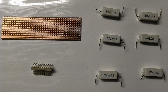
All the bits.
From the PC board cut a piece 10 holes by 40 holes and solder the header on one end. Next solder the resistors onto the PC board. The first resistor is connected between the first and second pins of the header. When positioning the resistors leave clearance on all sides to help heat dissipation. The second resistor is connected to the second and third pins of the header. The third to the third and fourth pins etc. The photos show the details.
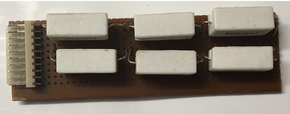
Top View
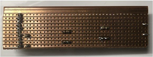
Bottom View
Operation is simple- just connect the balancing connector to the header and put in an open space. When discharging a battery the resistors will get hot so ensure there is adequate ventilation and clear space around the pack. The load is not polarity conscious so the pack can be connected either way to the load. In practice I partly discharge the battery by using it in a model either by flying or ground running the motor. This reduces the amount of capacity left in the battery and makes discharging easier.
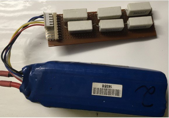
Discharger in Use